Garrafas de óleo vazando são mais do que uma bagunça em uma caixa – são reclamações de frete, clientes irritados, e margem perdida que você nunca planejou. A boa notícia é que a maioria desses vazamentos pode ser resolvida muito antes de um palete sair da sua fábrica.
Este guia mostra como construir um sistema de tampa de rosca resistente a vazamentos para óleo de motor e aditivos de combustível que sobrevive ao transporte real: bonés correspondentes, acabamentos de pescoço, e forros, discando na janela de torque certa, e validando tudo com drop, vibração, e testes térmicos.
Se você está lutando contra vazamentos recorrentes ou deseja garantir um design robusto antes de aumentar a escala, o POP a seguir orientará você passo a passo, desde a seleção do limite até a aprovação da remessa.
Por que o óleo do motor e os aditivos de combustível vazam durante o transporte
Os óleos de motor e os aditivos de combustível são particularmente propensos a vazamentos externos devido às suas propriedades físicas únicas combinadas com as rigorosas tensões de distribuição. Ao contrário da água, esses fluidos buscam ativamente caminhos de vazamento através de vários modos de falha distintos:
- Fluido “Rastejar” e Baixa Viscosidade: Os óleos têm baixa tensão superficial, permitindo-lhes “rastejar” sobem as roscas e passam através de aberturas microscópicas que, de outra forma, vedariam líquidos de maior viscosidade.
- Back-off induzido por vibração: A vibração constante de caminhões ou aeronaves atua como uma chave de impacto em câmera lenta. Esta tensão dinâmica afrouxa gradualmente a tampa se o atrito ou o perfil da rosca forem insuficientes.
- Expansão e Contração Térmica: Mudanças extremas de temperatura, como passar de asfalto quente para porões de carga frios, fazer com que a garrafa de plástico e a tampa se expandam e encolham em taxas diferentes. Este movimento pode quebrar temporariamente a interface do selo.
- Aumento de pressão: Aditivos voláteis podem gerar gases, e mudanças de altitude durante o frete aéreo criam diferenciais de pressão. Se a garrafa não puder ventilar ou suportar esta pressão, pode distorcer ou “inchar” e comprometer o selo.
- Conjunto de compressão de forro: Ao longo do tempo, forros de espuma podem perder sua capacidade de ricochete, conhecido como conjunto de compressão. Se o revestimento parar de empurrar contra a borda da garrafa, a força de vedação cai e permite que o fluido escape.
A diluição do combustível é uma forma de vazamento interno em que o combustível não queimado desvia dos anéis do pistão ou entra através de injetores defeituosos., comprometendo gravemente as propriedades lubrificantes do óleo do motor.
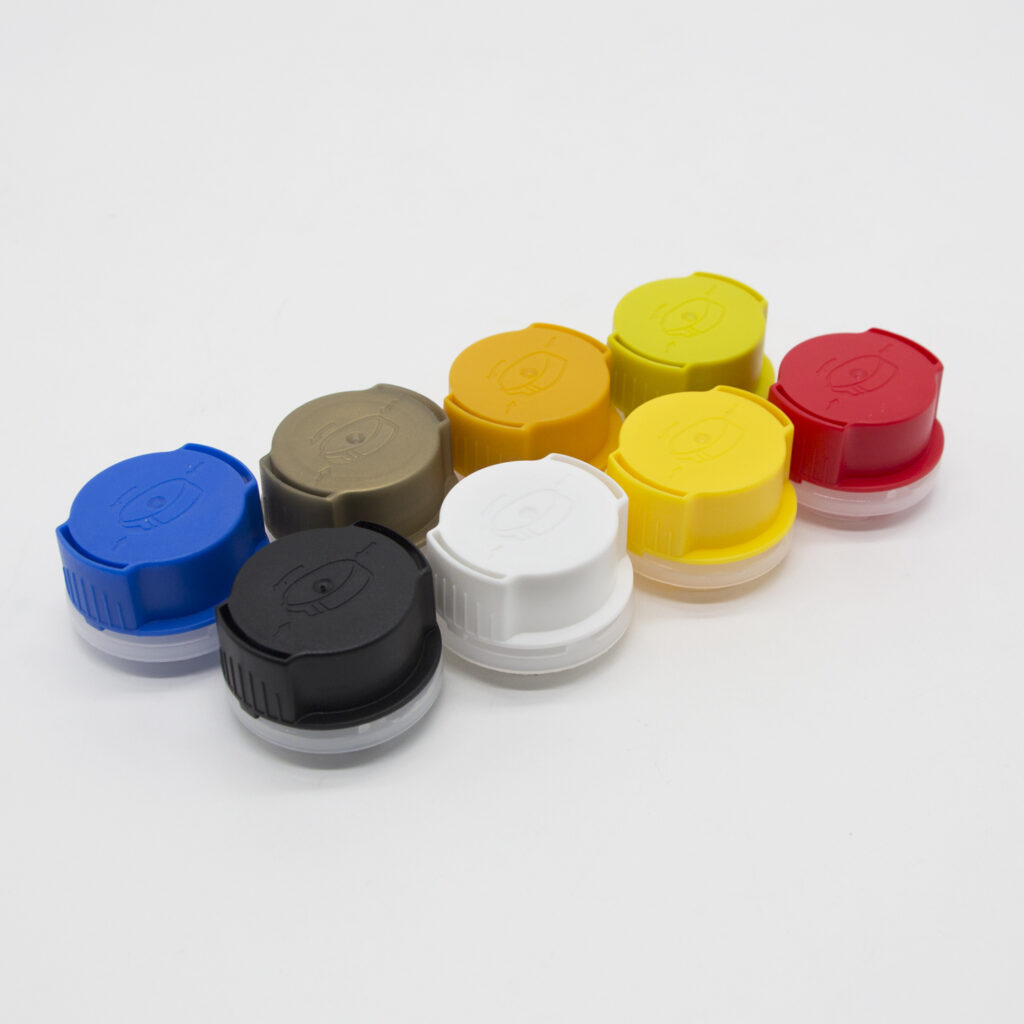
Principais características de design de tampas de rosca de plástico resistentes a vazamentos
A prevenção eficaz de vazamentos depende de engenharia integrada: o revestimento certo para o produto químico, um perfil de rosca que resiste ao retrocesso, e fabricação precisa para garantir uma superfície de vedação plana.
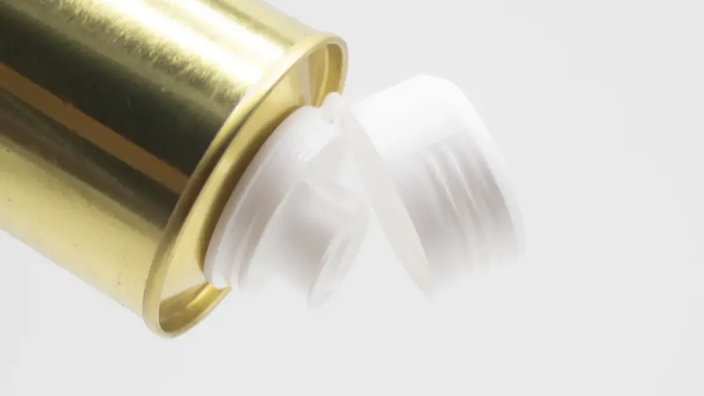
Integridade da vedação através do design e material do revestimento
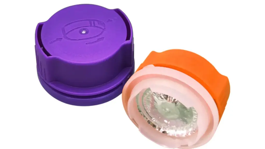
O revestimento é a barreira primária que impede o escape de fluido. A escolha do tipo certo depende da sua aplicação específica:
- Forros de espuma F217: Estes são o padrão da indústria para óleos de motor domésticos e de uso geral que exigem capacidade de vedação. Consistindo de um núcleo de espuma imprensado entre camadas de LDPE, eles oferecem excelente resiliência para ciclos de distribuição padrão e economia.
- Revestimentos laminados selados por indução: Estes são superiores para aditivos de combustível agressivos ou “Mão Única” remessas. Eles se ligam diretamente à borda do recipiente para criar uma vedação hermética, selo inviolável que resiste ao ataque químico e à alta pressão significativamente melhor do que apenas a espuma.
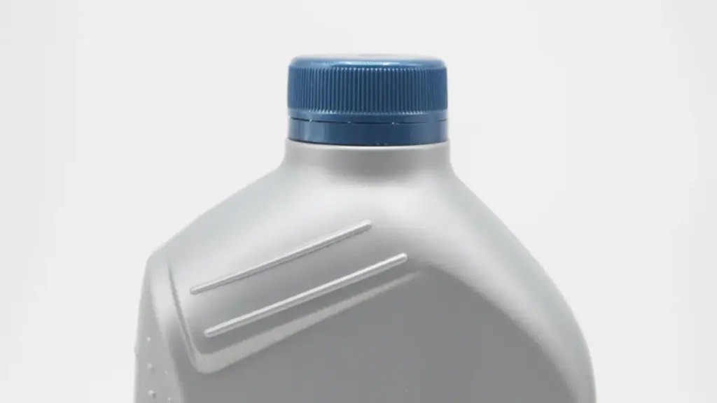
Engenharia de perfil de rosca para fechamento seguro
Para suportar vibração e pressão interna, use um perfil de rosca de contraforte. Seu formato assimétrico suporta alto empuxo axial, evitando que a tampa salte os fios ou se descasque sob carga. Crucialmente, certifique-se de que a tampa encaixe no gargalo da garrafa por um mínimo de 1.5 voltas completas. Qualquer coisa menos cria um ajuste instável que tende a se afrouxar quando sujeito a vibrações ou choques da estrada.
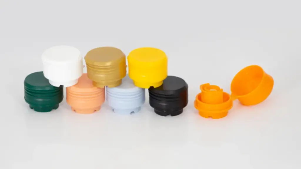
Seleção de Polímeros para Compatibilidade Química
O tampa de plástico a resina deve corresponder à química do produto. Polietileno de alta densidade (PEAD) é o padrão para óleos à base de petróleo devido à sua força e resistência química. Para aplicações de enchimento a quente ou aditivos solventes agressivos, Polipropileno (PP) é frequentemente preferido por sua maior tolerância ao calor e resistência à fissuração por tensão, garantindo que a tampa mantenha a força de vedação sem deformar ao longo do tempo.
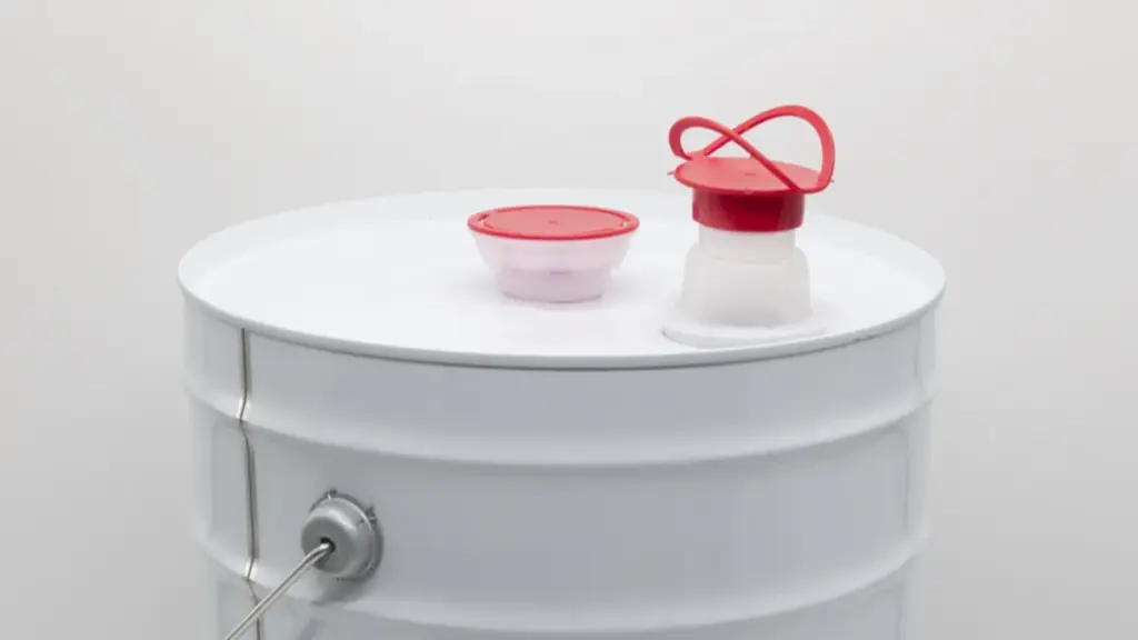
Gerenciamento de pressão com ventilação integrada
Óleos e aditivos muitas vezes expandem ou liberam gases durante picos de temperatura ou frete aéreo, criando pressão interna que causa vazamentos ou distorção da garrafa. Tampas ventiladas especializadas que incorporam uma membrana ePTFE resolvem isso, permitindo que o gás escape enquanto bloqueia o líquido. Isso equaliza a pressão para manter o formato do recipiente e a integridade da vedação em toda a cadeia de abastecimento.
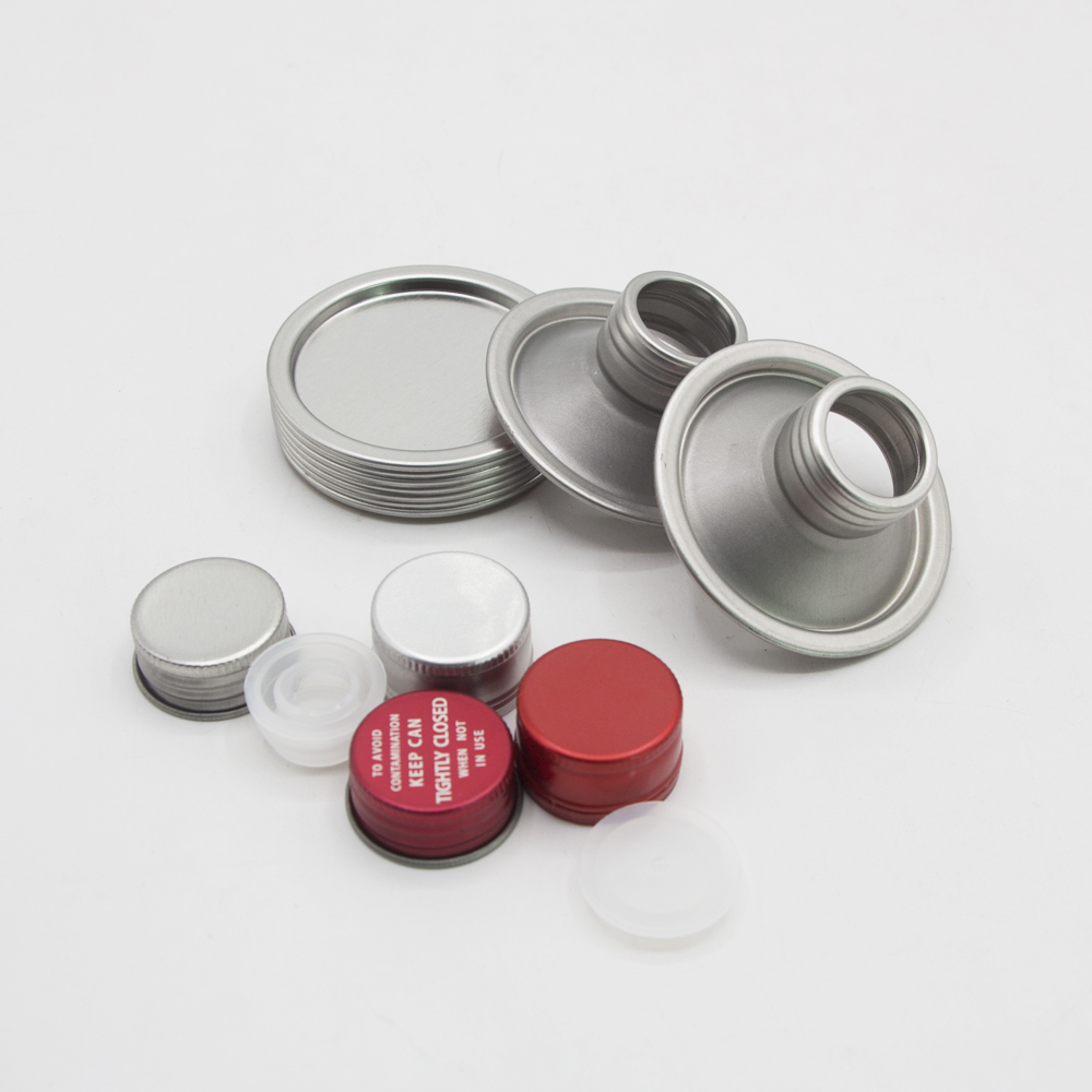
Tolerâncias de fabricação para superfícies de vedação
Um revestimento perfeito falha se a superfície abaixo dele apresentar falhas. O diâmetro da rosca T da garrafa e as dimensões da altura H devem ser consistentes, mas a terra selada, ou borda superior, é o mais crítico; requer uma tolerância de planicidade de ±0,05 mm para garantir compressão uniforme. Simultaneamente, as tampas devem estar livres de defeitos de moldagem, como flash ou fotos curtas. Mesmo imperfeições microscópicas na superfície de vedação podem se tornar caminhos de vazamento sob vibração de transporte.
Resumo dos recursos de design
| Recurso de projeto | Função Primária | Aplicação Comum |
|---|---|---|
| Forro de espuma F217 | Fornece um compressível, selo resselável. | Óleos e lubrificantes de motor de uso geral. |
| Forro de folha de indução | Cria um hermético, vínculo inviolável. | Aditivos de combustível agressivos e produtos de longa vida útil. |
| Perfil de rosca de contraforte | Resiste à pressão interna e ao recuo de vibração. | Recipientes sujeitos a altas vibrações ou mudanças de pressão. |
| Membrana de ventilação ePTFE | Permite a troca gasosa enquanto bloqueia o líquido. | Produtos que liberam gás ou são abastecidos em diferentes altitudes. |
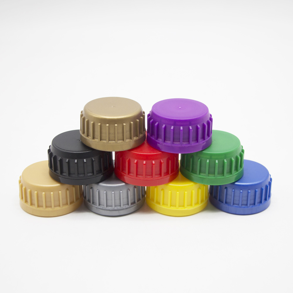
Elimine vazamentos com tampas projetadas com precisão
Tampas de rosca correspondentes, Acabamentos de pescoço, e forros
Um sistema à prova de vazamentos exige uma correspondência dimensional precisa entre a tampa e o frasco, junto com um material de revestimento que sobrevive à exposição química.
Medindo as dimensões do acabamento do pescoço para um ajuste adequado
Usando calibradores calibrados, verifique se a dimensão T e a dimensão H do frasco correspondem às especificações da tampa, como 28-410 ou 38-400. A tampa deve assentar totalmente na área de apoio da garrafa, sem atingir o ombro, o que impediria a compressão do revestimento. Verifique também o E-Dimension, ou diâmetro externo do pescoço, para garantir que as faixas invioláveis se encaixem corretamente sem emperrar.
Selecionando um revestimento com base na resistência química do produto
Combine o revestimento com a agressividade do fluido. Os óleos à base de hidrocarbonetos funcionam bem com revestimentos padrão F217 ou polpa/poli, mas os aditivos de combustível que contêm ésteres ou solventes fortes geralmente exigem revestimentos revestidos de PTFE ou folhas de indução de alta barreira para evitar inchaço e degradação. Evite sensíveis à pressão (PS) liners para líquidos, pois não possuem a resistência química e a força de ligação física necessárias para o transporte de petróleo.
Validando o envolvimento do thread e o torque do aplicativo
A validação do design vai além das dimensões. Confirme se o limite atinge pelo menos 1.5 voltas completas de engate para travar mecanicamente contra vibração. Além disso, realizar um teste de vácuo ou queda de pressão em amostras com torque. Uma montagem segura deve suportar a pressão interna, frequentemente em 95 kPa para conformidade com materiais perigosos, sem vazamento para confirmar que o torque e a compressão da camisa são suficientes.
Faixas de Torque de Aplicação e Torque de Remoção
Torque é a variável que ativa a vedação. Muito pouco causa vazamentos; muitas tiras de fios. Estabelecer e monitorar a janela de torque correta é essencial para uma produção consistente.
Torque de aplicação para vedação segura
O torque de aplicação alvo geralmente segue o diâmetro da tampa: 12–21 in-lbs para tampas de 28 mm, 17–26 pol-lbs para 38 mm, e até 25–43 pol-lbs para tampas de 63 mm. Esses valores garantem compressão suficiente do revestimento sem distorcer o plástico. No entanto, sempre trate os gráficos genéricos como ponto de partida e valide a configuração exata com seu fornecedor específico de tampa/garrafa para levar em conta as variações de atrito.
Tamanho da tampa e referência de torque
| Tamanho da tampa (milímetros) | Torque de aplicação recomendado (em libras) | Torque de remoção esperado (em libras) |
|---|---|---|
| 28 | 12 – 21 | 5 – 13 |
| 38 | 17 – 26 | 7 – 16 |
| 48 | 19 – 30 | 8 – 18 |
| 53 | 21 – 36 | 8 – 22 |
| 63 | 25 – 43 | 10 – 26 |
Observação: As faixas mostradas são para rosca contínua padrão (TC) bonés. Resistente a crianças (CR) ou fechamentos especiais podem exigir configurações de torque mais altas de acordo com as especificações do fabricante.
Torque de remoção imediata para verificações pós-limitação
Como os cappers automatizados são difíceis de ler diretamente, use o torque de remoção imediato verificado dentro de cinco minutos para CQ. Este valor normalmente deve ficar entre 5 e 12 pol-lbs para tamanhos padrão, que é aproximadamente 40–80% do torque de aplicação. Leituras abaixo desta faixa sugerem uma vedação fraca, propensa a vazamentos de trânsito; as leituras acima indicam torque excessivo que pode danificar a rosca.
Torque de remoção após conjunto de revestimento de 24 horas
Os revestimentos de plástico relaxam com o tempo. Após um período de permanência de 24 horas, o “torque de remoção” vai estabilizar, normalmente em 40–60% do torque de aplicação inicial. Esse “24Torque de remoção em horas” é o verdadeiro indicador da integridade do selo durante o prazo de validade. Se cair muito baixo, a tampa pode recuar sob vibração.
Fatores que afetam a consistência da medição de torque
Torque consistente depende de variáveis de controle. Variação do gargalo da garrafa, como tipo de resina ou acabamento superficial altera o atrito. O material do revestimento afeta a recuperação da compressão. Finalmente, a calibração do capper determina a repetibilidade. Verificações regulares da linha são obrigatórias para detectar desvios antes que causem um derramamento.
Simulação de Transporte: Derrubar, Vibração, e testes de temperatura
Você não pode confiar apenas no torque estático. Simulação de transporte, como ISTA 3A, submete sua embalagem às tensões dinâmicas da cadeia de suprimentos para provar que ela não vazará.
Preparação e instrumentação de amostras de teste
Para garantir resultados válidos, a configuração do teste deve refletir a realidade:
- Configuração de amostra: Teste exatamente o que você envia. Seguro preenchido, limitado, e amostras em caixas para a bancada de teste para evitar movimentos irrealistas.
- Instrumentação: Anexe acelerômetros para medir forças G e termopares para monitorar a exposição térmica, garantir que o estresse físico corresponda ao perfil alvo.
- Inspeção de Linha de Base: Realize uma inspeção visual pré-teste detalhada para estabelecer uma linha de base. Isto é crucial para distinguir entre imperfeições pré-existentes e vazamentos reais pós-teste.
- Parceiro de validação: Se mesas de vibração ou testadores de queda internos não estiverem disponíveis, a parceria com um laboratório terceirizado certificado pela ISTA é o caminho padrão para a conformidade.
Tipos e critérios de teste de simulação de transporte
| Tipo de teste | Finalidade da Simulação | Métricas-chave & Critérios de aprovação |
|---|---|---|
| Teste de queda ISTA | Simula quedas e impactos acidentais durante o manuseio e transporte. | Altura de queda com base no peso do pacote. Sem vazamentos, rachaduras, ou perda de integridade da vedação após impactos. |
| Senoidal & Vibração Aleatória | Replica tensões do caminhão, trilho, ou transporte aéreo. | Níveis de força G, varreduras de frequência, duração. Sem afrouxamento da tampa (recuo) ou fadiga do selo. |
| Choque Térmico & Ciclismo | Simula a exposição a temperaturas ambientais extremas. | Faixa de temperatura (-20°C a +60°C), taxas de rampa. Sem degradação de material ou vazamentos relacionados à pressão. |
Execução de sequências de teste de queda padrão ISTA
Os testes de queda replicam os impactos do manuseio manual e da classificação. Seguindo os protocolos ISTA, deixe cair o pacote de uma altura especificada pelo peso em superfícies planas, bordas, e cantos. Os critérios de aprovação são simples: vazamento zero. Qualquer sinal de retirada do limite, rachaduras, ou umidade constitui uma falha que requer revisão do projeto.
Aplicação de perfis de vibração sinusoidal e aleatória
Para imitar o transporte rodoviário e aéreo, use uma mesa agitadora para aplicar perfis de vibração aleatórios, muitas vezes com cargas superiores para simular o empilhamento. Execute esses perfis em todos os três eixos pela duração especificada para verificar dois modos de falha principais: recuo da tampa, onde a vibração afrouxa gradualmente o fechamento, e ressonância, que pode quebrar o gargalo da garrafa.
Simulação de choque térmico e condições de ciclismo
As verdadeiras cadeias de abastecimento não são controladas pelo clima. Testes de ciclagem térmica variando de -20°C a +60°C forçam o frasco e a tampa a expandir e contrair repetidamente. Isso tensiona a interface do selo. Uma embalagem bem-sucedida deve manter sua vedação sem que o plástico sofra um conjunto permanente que afrouxe a tampa ao retornar à temperatura ambiente.
Lista de verificação pré-embarque antes de aprovar uma nova tampa de rosca
Antes da produção em massa, siga esta lista de verificação para validar a compatibilidade, dimensões, e desempenho.
Etapa 1: Verifique a compatibilidade do polímero e do material do revestimento
Confirme a resina da tampa, como PEAD ou PP, e o tipo de forro, se F217, indução, ou PTFE, são quimicamente compatíveis com seu óleo ou aditivo específico. Materiais incompatíveis podem inchar, rachadura, ou dissolver com o tempo, levando a vazamentos retardados que só aparecem depois que o produto está em um depósito.
Etapa 2: Inspecione as tolerâncias dimensionais e o envolvimento da rosca
Verifique cada lote em relação às especificações. Medida T, H, e dimensões E e verifique o nivelamento da área de vedação. Teste manualmente as tampas para garantir um rosqueamento suave com pelo menos 1.5 turnos de noivado. Também, inspecionar visualmente se há rebarbas de moldagem ou disparos curtos que possam perturbar a vedação.
Etapa 3: Realizar testes de torque e pressão/vazamento
Validar dados de desempenho. Confirme se o torque da aplicação de produção produz um torque de remoção aceitável imediatamente e após 24 horas. Finalmente, passar por um teste de vácuo ou queda de pressão em aproximadamente 95 kPa para provar que a vedação está hermética e pronta para os diferenciais de pressão do transporte aéreo ou terrestre.
Proteja suas remessas com fechos projetados com precisão
A prevenção de vazamentos começa na prancheta, mas o resultado final depende inteiramente da execução do seu fornecedor. No introduzido, nós nos dedicamos mais 15 anos para fabricar tampas de plástico e metal especificamente para o indústria de cuidados automotivos. Entendemos os riscos do seu negócio. Se um encerramento falhar a meio caminho do seu destino, custa muito mais do que o preço da embalagem – custa a confiança do seu cliente.
É por isso que nos recusamos a cortar custos. Desde perfis de rosca de contraforte estritamente controlados até 100% testes de pressão automatizados, cada tampa que sai de nossas instalações é construída para sobreviver aos rigorosos desafios de distribuição descritos neste guia. Atuamos como seu parceiro técnico, pronto para ajudá-lo a combinar o revestimento e o material certos para sua formulação química específica.
Pequenos problemas de embalagem não deveriam se tornar grandes dores de cabeça logísticas. Se você deseja melhorar a integridade do seu selo ou precisa de uma segunda opinião sobre sua configuração atual, entre em contato conosco hoje para discutir suas necessidades. Nossa equipe de engenharia está pronta para fornecer consultoria técnica e enviar amostras para seus próprios testes de validação.
Perguntas frequentes
Por que minhas garrafas de óleo de motor vazam durante o transporte?
Vazamentos geralmente resultam de uma combinação de retorno de vibração, torque insuficiente, ou conjunto de compressão de liner. A expansão térmica e as mudanças de pressão devido à altitude também empurram o fluido através de imperfeições microscópicas se a vedação não for robusta.
Quão apertadas devem ser as tampas de rosca nas garrafas de óleo?
Tipicamente, 12–21 in-lbs para tampas de 28 mm e 17–26 in-lbs para tampas de 38 mm. Sempre verifique essas faixas com seu fornecedor de tampas e confirme verificando se o torque de remoção de 24 horas permanece entre 40–60% do torque de aplicação.
Que testes posso fazer para verificar a resistência da vedação da tampa?
Use queda de vácuo/pressão para integridade da vedação e teste de queda/vibração ISTA para durabilidade do transporte. Também, monitore o torque de remoção regularmente para garantir a consistência da linha de produção.
Preciso de vedações de indução, bem como tampas de rosca para óleo?
Para óleos padrão, um bom forro de espuma geralmente é suficiente. No entanto, para aditivos de combustível, solventes, ou frete aéreo, selos de indução são fortemente recomendados para fornecer uma vedação hermética, barreira inviolável contra vazamentos.
Como posso impedir que garrafas de aditivo de combustível vazem no transporte?
Use um revestimento quimicamente resistente, como PTFE ou folha de indução, garantir 1.5+ voltas de linha, e validar configurações de torque. Se a liberação de gases for um problema, mude para tampas ventiladas para equalizar a pressão.
Por que algumas tampas só vazam após vibração ou trânsito longo?
A vibração causa desgaste dinâmico e recuo, enquanto o ciclo térmico relaxa o plástico. Estas forças degradam lentamente uma vedação marginal que parecia boa na linha de produção, eventualmente abrindo um caminho de vazamento.